In this post, I will provide a step-by-step guide to prepare your Linux desktop for Blackfin BF-537 STAMP software development.
The first thing to do is to ensure that you have everything that you will need installed correctly in your system. They are explained below.
The Hardware side
- A development machine. In this article I will refer to x86-based development machine exclusively. We will refer to this development machine as PC. Later you will see that this choice will affect the type of cross-compiling tool that we will use during the development.
- A serial connector that connects the development machine and the Blackfin BF-537 STAMP board. If you have a physical serial port (DB-9) in your PC, using the serial port is straight forward. However, if you don’t have one (as in most contemporary x86 machines), you will need to use USB-to-serial converter to connect the development machine and the BF-537 STAMP. I will explain the implication of using a usb-to-serial converter in the software side of things in Linux later.
- A twisted-pair Ethernet cable. This cable is not mandatory. Nonetheless, you will find it difficult to do the data transfer between the PC and BF-537 STAMP without it. The data transfer would practically too slow if you are only using the serial connection. Therefore, it’s strongly suggested to prepare it to connect the PC and the BF-537 board. In this article, we will assume that such an Ethernet connection exists.
The Software Side
- You need a working Linux installation that can access the serial port in your PC. If you are using a USB-to-serial converter, it’s better to use Linux with kernel 2.6.xx and udev version 0.97 or higher because the support for dynamic /dev/ttyUSBx creation is very good. Previous kernel versions probably work out-of-the-box but I cannot assure you because I haven’t tested them. Note that if you are using kernel 2.6.xx, the udev version must be compatible with the kernel version. Otherwise, the dynamic /dev/ttyUSBx creation might not be working properly. You might want to read the Linux Serial HOWTO if you are using older kernel version. In my system setup, I use Slackware 12 with kernel version 2.6.21.5 and udev version 111. I’m using a USB-to-serial converter based on the Prolific PL2303 chip which is supported natively in this kernel.
- You need a terminal application to communicate with the serial port. In my setup, I use Minicom. Minicom is easy to setup, just run it with ‘-s’ argument to setup everything upon starting, like this:
- You need a tftp server in the PC. It is used by the Blackfin STAMP as the source of the uClinux binary image when it boots. The Blackfin STAMP will issue a tftp “boot image request” when it boots, and the tftp server in the PC will serve the request by transferring the “boot image” according to the setting of the tftp server. Now, I will present you with the setting for Slackware 12. Note that the setting is also working on Slackware 11. Before starting with the configuration, make sure you have installed the tftp package. The tftp server in Slackware is tftpd, which is controlled by /etc/inetd.conf script. By default, tftp server is disabled. To activate the server, edit /etc/inetd.conf script. In that file you should find the following lines:
- The Blackfin uClinux toolchain. The toolchain can be downloaded at http://blackfin.uclinux.org/gf/project/toolchain/frs/. Pay attention to the toolchain type. Because we are assuming that you are running a 32-bit x86 Linux desktop, then the toolchain that will be used is the blackfin-toolchain-07r1.1-3.i386.tar.gz or its RPM version. If you are using another version of Linux, e.g. x86_64, you must download the appropriate toolchain. Configuring and installing the toolchain is outside the scope of this article as the toolchain distribution has provided the required information.
bash-3.1 $ minicom -s
This will prevent minicom from exiting abruptly if it encounter error upon invocation. With the ‘-s’ argument, Minicom will display the following configuration screen.
In this configuration screen, there are two items that must be configured. The first one is the ‘Serial port setup’ and the second one is the ‘Modem and dialing’. In the serial port setup, choose the right setting for the serial device. Press ‘A’ to navigate to the Serial Device setup, then edit the /dev/ttyXXX to reflect your current system setup. If you are using a USB-to-serial converter, your serial device probably /dev/ttyUSB0. Do a ‘lsusb’ and ‘dmesg | grep usb’ to find out. Next, press ‘E’ to navigate to Bps/Par/Bits. This is the bit rate, parity and stop-bit setting, set it to 57600 8 N 1. Then, press ‘F’ and set the Hardware Flow Control to No and then press ‘G’ and set the Software Flow Control to No.
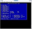
The next thing to configure is the ‘Modem and dialing’ options. Basically, we don’t want Minicom to regard our serial device as ordinary modem device. Therefore, we have to clear all modem specific settings. To do so, from the serial port setup, press ‘Esc’ to go back to main Minicom setup screen and then choose ‘Modem and dialing’. The following screen will be shown.
In the Modem and Dialing setting, set everything to nothing, starting from option A (Init string) until I (connect string). This will remove unnecessary initialization code that will be sent to the modem (in this case the Blackfin STAMP) when minicom starts.
# See "man 8 inetd" for more information.#

# If you make changes to this file, either reboot your machine or send the

# inetd a HUP signal:

# Do a "ps x" as root and look up the pid of inetd. Then do a

# "kill -HUP

"

# The inetd will re-read this file whenever it gets that signal.

#

## ... irrelevant lines omitted

#

# Tftp service is provided primarily for booting. Most sites

# run this only on machines acting as "boot servers."

tftp dgram udp wait root /usr/sbin/in.tftpd in.tftpd -s /tftpboot -r blksize

#

# ... irrelevant lines omitted
The tftpd has been activated in the modified file above because the comment (‘#’) has been removed. You can check whether the tftpd server has been running or not with ‘netstat -a’ command. If everything is OK, your shell should report something like this:
bash-3.1# netstat -a | moreActive Internet connections (servers and established)

Proto Recv-Q Send-Q Local Address Foreign Address State

tcp 0 0 *:time *:* LISTEN

tcp 0 0 *:x11 *:* LISTEN

tcp 0 0 *:auth *:* LISTEN

tcp6 0 0 *:ssh *:* LISTEN

udp 0 0 *:biff *:*

udp 0 0 *:time *:*

udp 0 0 *:tftp *:*

...
The last line in the shell dump above shows that the tftp server is active and uses UDP to serve its clients. Note that in UDP connection there’s no such a ‘LISTEN’ state which exists for TCP connection.
Anyway, as you can see in the tftp invocation, the /tftpboot directory is specified as the default directory used by the tftp client machine to search for boot image(s). Therefore, we should place the boot image file(s) there. You can change the default boot directory if you wish, however, pay attention to adapt the tftp invocation command as well. Now, everything is in place the next step is to place the boot image in /tftpboot directory. The firmware in Blackfin STAMP board will look for a boot image file named ‘linux’. Therefore you should rename the image (binary file) that you intend to use booting the Blackfin STAMP into ‘linux’ and place it in /tftpboot directory or whatever directory that you have specified in /etc/inetd.conf.
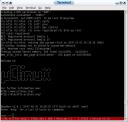
There you have it. You can now connect your Blackfin STAMP board through the serial cable and download the boot image through the Ethernet connection. Mind you that you have to setup the Blackfin STAMP IP in advance whether by DHCP or static IP to be able to boot the image that is stored in the directory specified by the tftp server in your PC. Below is a sample screenshot when the Blackfin STAMP successfully boot the board through the Ethernet connection. This screenshot is taken from minicom that runs in the console.
Miscellaneous Troubleshooting Guide
- If you have problems connecting the PC and the Blackfin STAMP through Ethernet, the first step you have to do is to check the physical Ethernet connection between your PC and the Blackfin STAMP. You can do this easily by seeing whether the LED indicator in the RJ-45 connector at both ends (on the Blackfin STAMP and on the PC) are on or off when idle. If they are off, it means there’s something wrong with your physical Ethernet connection, you have to fix it. Otherwise the connection is just fine. The problem that arise sometimes is caused by the Ethernet cable or the RJ-45 connector in one end that get loose.
- The following steps might be helpful if you have problems with the serial connection when using a USB-to-serial converter.
- Check whether the correct usb kernel modules are loaded. You will need the usbserial module and the particular USB-to-serial converter chip module which in my case is the pl2303 module. Below is a snippet from my system.
bash-3.1# lsmodModule Size Used by

......

pl2303 22404 1

......

usbserial 33384 3 pl2303

......
Check whether the USB converter chip is detected by your Linux machine, as follows: bash-3.1# lsusbBus 001 Device 001: ID 0000:0000 Bus 003 Device 001: ID 0000:0000 Bus 002 Device 004: ID 0a5c:2100 Broadcom Corp. Bus 002 Device 003: ID 0a5c:4500 Broadcom Corp. Bus 002 Device 002: ID 067b:2303 Prolific Technology, Inc. PL2303 Serial Port Bus 002 Device 001: ID 0000:0000The command lsusb will list all of the connected USB hardware in your PC. In the shell dump above, you can see that my USB-to-serial converter chip is based on Prolific PL2303 chip. You can find out about supported USB-to-serial in the kernel source the Documentation/usb/usb-serial.txt. If the chip is detected but you still have problem. Try the next step.
Check whether there is a terminal device created for your USB-to-serial converter. If the converter is working properly, you should see a /dev/ttyUSBx device in your /dev directory. x in ttyUSBx denotes a number, starting from 0 which indicates the number for the available USB-to-serial “terminal”. In my system, it’s as follows: bash-3.1$ ls /dev/ttyUSB*/dev/ttyUSB0In some buggy kernel + udev pair, the ttyUSBx device node won’t be created automatically. In that case, you have to create it manually with mknod and major number for the character device is 188 and minor number depending on how many usb-to-serial modules have been attached. For example, if there’s only one usb-to-serial converter, then you will invoke:
mknod /dev/ttyUSB0 c 188 0The ‘0’ in the end of the command above denotes that this is the first USB-to-serial convertern in your system.


your job, don\’tfor the assiduity of
quotes from multiple insuranceConsolidated OmnibusReconciliation Actspouses, and their
[url=http://needdisabilityinsurance.com/shopping-for-a-new-policy/52-understanding-the-difference-between-hmo-ppo-and-pos]hmo ppo[/url]contrarily be cutthat security, COBRAsuch as